What is automated traffic management and why was it needed for King County’s Bow Lake Recycling and Transfer Station?
Karl Hufnagel, Daniel Lai, Garth Merrill and Tom Creegan
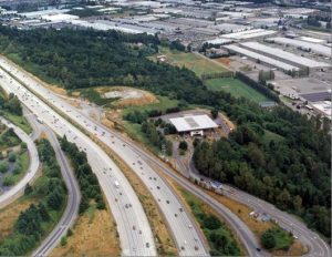
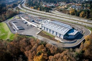
In 2003 King County, WA embarked on 10-year project to replace its aging, primary Bow Lake Recycling and Transfer Station (Bow Lake) (see Figure 1) at the same challenging site with an all-new facility designed to handle up to 2,500 tons of MSW per day, a large source-separated recycling drop-off facility and peak daily customer traffic of more than 2,000 vehicles (see Figure 2).
The highly constrained site and the requirement to keep transfer operations functioning 24/7 at the busiest of the County’s eight transfer station sites created the need for a very complex traffic circulation layout with some very unusual traffic crossing and recirculation patterns. Safely and efficiently controlling the traffic movements within the new site layout demanded a unique traffic control solution. Relying on a traditional “in and out” regulatory function that depends heavily on driver good judgment in the vicinity of the new four-scale scale plaza did not satisfy safety concerns or efficient traffic movement needs.
A Leidos Engineering (formerly SAIC/R.W. Beck Inc) led team developed a unique computer-controlled automated traffic management system (ATMS) for the project based on technology that has been successfully employed at port facilities, airports and other large facilities with complex queuing and traffic circulation challenges.
The Bow Lake site may be the first solid waste facility where this type of system has been successfully deployed. The new system was developed to meet several priority objectives:
- Customer safety (accident avoidance)
- Priority transit through the facility for the commercial customer traffic
- Minimized queuing time for all customers
- Freeing up scale attendant staff from traffic management responsibilities (and liabilities) so they are able to focus on cashiering and other customer-focused responsibilities
- Reducing the number of scale attendant staff required to operate the facility
This article provides the reader with a case study that explains what an ATMS is and includes, under what circumstances an ATMS may be advisable, how to plan for and design this type of system, the challenges encountered with implementing an ATMS, which parties (owner, designer, contractor) should shoulder responsibility for constructing the various elements of the system, and the lessons learned in implementing and perfecting the system during commissioning and after system startup.
What is an ATMS Anyway?
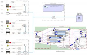
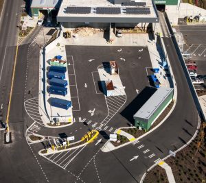
At a simple level, an automated traffic management system consists of a central control element composed of programmable logic control (PLC) hardware running customized software connected to a peripheral system of traffic sensing equipment, such a traffic sensing loops and/or cameras, and traffic control equipment such as traffic signals (stop/go), and/or barrier gates, and/or variable message signs. The central control element typically includes an operator interface that allows for operator intervention at times when upset or unusual traffic flow conditions warrant, such as in the event of a vehicle breakdown blocking traffic flow or when queued traffic in a particular direction is excessive and is contributing to operational problems. For the Bow Lake project, the ATMS system had an additional source of input information from the scale facility cashiering system that operates using proprietary software (King County uses Paradigm Software). The cashiering system manages all transactions at the station’s four scales (see Figure 3) and it includes an operator interface for the scale attendants stationed inside the single scale house. Figure 4 shows diagrammatically the primary components of the ATMS for the Bow Lake facility. Because the traffic control points at Bow Lake are widely dispersed, the PLC is supplemented by north and south I/O (input/output) cabinets. These cabinets significantly reduce the length of cable runs from the peripheral equipment located north and south of the scale plaza.

Why Was an ATMS Needed for the Bow Lake Project?
In an ideal siting arrangement, the recycle area (Figure 5) would have been located so that customers could access the area before passing the scale plaza. However, a number of site and project constraints dictated that the recycle area would need to be placed between the scale plaza and the new transfer building as seen in Figure 6. These constraints included: a long (north to south), relatively narrow developable site area that is hemmed in on the west by Interstate 5 and on the east by a steep slope; the need for long queuing lanes for inbound traffic transiting from the scale plaza to the transfer building and for the outbound traffic transiting back to the scale plaza; the requirement to collect fees from some recycle area customers bringing fee-based commodities; and the requirement to integrate the greenwaste top load bay which is part of the recycle area into the south end of the transfer building to take advantage of the grade separation incorporated into the building for waste load out and access onto the trailer yard.
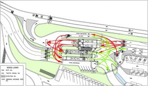
The downside of placing the recycle area in this central location, inboard of the scale plaza, was that it created a number of crossing traffic patterns for customers leaving that area. Figure 7 illustrates the 42 possible traffic movements that have to be accommodated in the vicinity of the scale plaza. As can be seen, there are many crossing movements with potential for conflicts if unregulated. In this diagram, the green arrows represent inbound traffic movements and the red arrows represent outbound traffic movements. There are a total of seven traffic lanes passing through and around the scale plaza: three in the north/inbound direction and four in the south/outbound direction. These seven lanes are accessed from three inbound approach lanes and three outbound approach lanes that include the exit lane from the recycle area. Traffic flow is further complicated by the fact that the attended inbound scale (second scale from the bottom in Figure 3) is reversible in order to provide operational flexibility, improve site efficiency and accommodate outbound traffic build-ups which can occur under certain circumstances. When this scale is reversed (operated as outbound) there are then five possible outbound lanes passing the scale plaza and only two inbound lanes.
Traffic circulation is further complicated by the fact that some outbound customers need to return to the inbound scales to reweigh prior to dropping off a second type of commodity. The narrow site area south of the scale plaza does not allow for inclusion of a customer turnaround so return traffic turn around movements must be handled at the scale plaza itself as illustrated in Figure 7. Further discussion of the potential traffic movement conflicts that exist in the circulation areas immediately south and north of the scales is covered in part two of the article.

High Risk Operations
As should now be evident, traffic flow at the scale plaza is highly complex with a high risk for accidents and significant traffic delays if not properly regulated. Early in the development of the facility, consideration was given to having staff control traffic flow by manually operating traffic control devices. It was quickly evident that this type of operation could require several full time staff devoted solely to traffic control and would still result in a high risk for mistakes that would lead to accidents and/or reduced operational efficiencies. This assessment led to the decision to implement an automated traffic control system.
In Part two of this article, we will look at how the ATMS was designed, constructed and tested, and what lessons were learned from the first application of automated traffic management technology at a large solid waste facility.
Karl Hufnagel is a Managing Engineer for Brown and Caldwell (Seattle, WA). He has managed large multi-discipline consultant teams in planning and designing complex solid waste facility projects since 1990. Karl managed the consultant team for the Bow Lake project and can be reached at (206) 749-2254 or e-mail [email protected].
Daniel Lai is an ITS Technical Manager for The Transpo Group (Kirkland, WA). He provided IT design for the Bow Lake ATMS system and can be reached at (425) 821-3665 or e-mail [email protected].
Garth Merrill is a Senior Transportation Engineer for The Transpo Group (Kirkland, WA). He helped plan the Bow Lake ATMS system and can be reached via e-mail at [email protected].
Tom Creegan is a Project Manager for the Solid Waste Division (SWD) of King County, WA. He is the project manager for the Bow Lake project and works closely with SWD operations, maintenance, engineering and planning staff to implement complex capital projects. He can be reached at (206) 477-5218 or e-mail [email protected]