A Rainwater Toe Drainage System, by removing water from the final cover drainage layer, eliminates the possibility of pore pressure build up in the drainage layer at the lower portions of the landfill slope, thus creating a condition that promotes stability of the slope.
Ali Khatami, Ph.D., P.E.
Rainwater falling on landfill slopes is managed by various systems developed at the stage of the design/permitting of the landfill. The surface water runoff is managed through swales and downchute systems on the slope, while a portion of the water percolates into the final cover soil layer. The collected water in the swales is conveyed to downchute pipes and then to the landfill perimeter storm water management system. Rainwater that percolates into the final cover generally exits the final cover in two different ways: 1) a portion of the water stored in the final cover soil layer evaporates out of the final cover; and 2) water that percolates through the final cover soil layer reaches the drainage layer overlying the cover geomembrane. By design, the final cover geomembrane is generally textured to improve the interface friction within the final cover structure. The drainage layer may be a granular drainage layer or a synthetic drainage layer. The widely accepted synthetic material used for the final cover drainage layer is geocomposite. Geocomposite consists of a single layer of geonet heat bonded on both sides to geotextiles. The lower geotextile acts as the friction layer against the underlying textured geomembrane, and the upper geotextile acts as the filter to prevent soil particles from entering and clogging the geonet, which acts as the drainage medium. The subject of this article is related to those final covers including a synthetic drainage layer overlying a geomembrane barrier layer.
Managing Rainwater
Rainwater reaching the geocomposite in the final cover percolates through the upper geotextile and flows down the slope primarily through the geonet layer of the geocomposite. The water in the geonet at the bottom of the landfill slope must be managed in such a manner that water is not backed up in the geonet. The backing up of water in the geonet causes saturation of soil in contact with geocomposite, and saturation could potentially cause instability issues within the final cover. The best management practice for managing water in the geonet would be to provide a collection system at the lowest point of the slope to efficiently remove water from the geocomposite and drain it out of the final cover.
In the event that depressions exist in the landfill slope by design (such as benches, terraces, or access roads) with a low point toward the landfill slope on the bench, it is anticipated that the geocomposite conforming to the depression will have a low point as well. Water can get trapped in the geocomposite low point and back up in the geonet if a collection and removal system for the water in the geocomposite is not provided. This article only addresses the collection and removal system at the toe of the landfill slope near the perimeter berm of the landfill. A collection and removal system at the low point of a terrace on the landfill slope may be similar to the system discussed below with slight variations to address the width and inward slope of the terrace. This subject is not discussed in this article.
The Rainwater Toe Drain System
A collection system, called the “Rainwater Toe Drain System” or RTDS, was developed approximately 15 years ago. Up to that point in time, the water in the geocomposite was directly discharged out of the lower edge of the geocomposite exposed to the open environment or buried in a gravel bedding on top of the landfill perimeter berm. Over time, it was proven that such designs could potentially fail to effectively remove water from the geocomposite due to the clogging of the geocomposite end point. Dirt accumulation, soil from erosion of cover soils from higher up on the slope, or vegetative growth around the geocomposite end point clogged the pathway for water out of the geocomposite and caused saturation at the toe of the landfill slope at the perimeter berm. The RTDS proved to be an efficient system requiring no maintenance, while performing effectively for an extended period of time. Like almost every new idea, the design had to be upgraded over time to improve performance and reduce maintenance of the system. Figure 1 illustrates the most efficient version of the RTDS with respect to location and geometry, which was adopted by clients as a standard feature in all of their final cover systems.
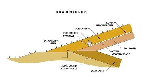
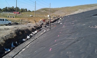
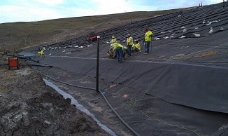
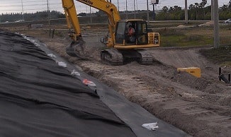
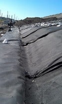
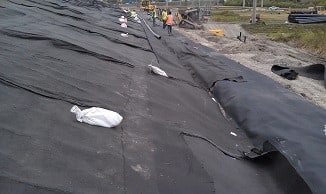
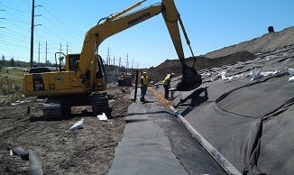
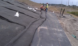
The RTDS includes a geomembrane flap (RTDS flap) welded to the cover geomembrane along a sloping line a short distance above the lowest point of the landfill slope. Prior to the welding of the flap, a sloping line is marked on the cover geomembrane by a surveyor or the installer of the RTDS flap (see Photo 1). The sloping line extends from a low point to a high point with an approximately 2 ft. elevation difference between the low and high points. The lateral distance between a low point and a high point may be 150 ft., with a 300-ft. distance between each two consecutive low or high points. The RTDS flap may be only 7 ft. wide and welded on one side along the line marked on the cover geomembrane (see Photo 2). The other side of the RTDS flap is positioned over a small soil berm constructed over the cover geomembrane at the toe of the landfill slope (see Photo 3) such that a depression is created above the RTDS flap (see Photo 4) for positioning a perforated pipe (RTDS pipe) encased in gravel and wrapped in geotextile (RTDS burrito) inside the depression (see Photos 5-7). The small berm is constructed such that the extrusion weld of the RTDS flap is located at the bottom of the depression. The sloping extrusion weld of the RTDS flap provides the slope along the RTDS burrito for the flow of water inside the RTDS pipe.
The geocomposite drainage layer on the slope is terminated at the bottom of the LTDS flap depression (Photo 4) and the RTDS burrito is positioned directly above the end point of the geocomposite. With this design, water in the geocomposite drains directly into the RTDS burrito and into the RTDS pipe. No soil should exist between the geocomposite and the bottom of the burrito, otherwise a hydraulic bottleneck will be created that will significantly reduce efficiency of the system.
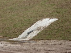
Water in the RTDS is drained out of the final cover through drain pipes (lateral pipes) positioned perpendicular to the perimeter berm alignment. The lateral pipes are positioned at 300-ft. spacing (at the converging low ends of two adjacent 150 ft. long RTDS) along the landfill perimeter berm. The lateral pipe extends from the RTDS flap to the perimeter ditch, sloping toward the perimeter ditch to create gravity flow out of the RTDS. Each lateral pipe is connected to the RTDS burrito at the high end of the pipe by penetrating the RTDS flap, and discharges to the landfill perimeter ditch at the low end of the pipe. The penetration through the RTDS flap must be booted to prevent water from leaking into the perimeter berm structure. An erosion control mat should be installed at the low point of the RTDS lateral pipe to eliminate soil erosion at the point of discharge (see Photo 8).
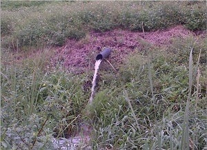
Photo 9 shows the RTDS in service and depicts the amount of water that can flow out of a single lateral pipe after a large storm. If the RTDS did not exist at the toe of the landfill slope, the water in the geocomposite would have been trapped in the final cover and would have potentially caused instability issues for the final cover, or at least created a washout near the lower portion of the slope due to the backing up of water in the cover geocomposite, and causing it to enter the soil above the geocomposite.
Keeping Stability
The construction cost of an RTDS varies from project to project depending on the components included in the design. The unit cost of construction may vary from $30 to $40 per linear foot.
The expense may seem an additional cost item to the construction of a final cover system without a RTDS; however, through the construction of numerous landfill final cover systems with the RTDS, it has proven to be an important component for keeping the final cover intact and stable on the slope for as very long periods of time.
The RTDS was specifically developed to drain the final cover drainage layer at the toe of the landfill slope. A simple construction technique was developed to facilitate construction of the RTDS. Through numerous final cover construction projects, contractors have not indicated that the construction technique is cumbersome or complicated. The RTDS, by removing water from the final cover drainage layer, eliminates the possibility of pore pressure build up in the drainage layer at the lower portions of the landfill slope, thus creating a condition that promotes stability of the slope.
Ali Khatami, Ph.D., P.E. is a Vice President and Project Manager for SCS Engineers (Coconut Creek, FL). He has more than 30 years of research and professional experience in the areas of mechanical, structural and civil engineering. Dr. Khatami has over two decades of experience in the lifecycles of environmental projects—from design and permitting to operations to landfill closure. He has acquired extensive experience and knowledge in the areas of geology, hydrogeology, hydrology, hydraulics, construction methods, material science, construction quality assurance (CQA) and stability of earth systems. He has applied this experience in the siting of numerous landfills. Dr Khatami can be reached at (954) 571-9200 or via e-mail at [email protected].