How was the automated traffic management system for King County, WA Bow Lake Recycling and Transfer Station developed and what lessons were learned?
Karl Hufnagel, Daniel Lai, Garth Merrill and Tom Creegan
In part one of this article, which appeared in the July 2015 edition of Waste Advantage Magazine, we discussed what an automated traffic management system (ATMS) is, and why the system was needed for the King County Bow Lake Recycling and Transfer Station. In part two, we will discuss how the ATMS was designed, constructed and tested, and what lessons were learned from the first application of automated traffic management technology at a large solid waste facility.
ATMS Design Approach
Due to the complex traffic conditions identified, traffic engineering and automation specialists from Transpo Group and ICX/360 Surveillance were brought onto the design team to design an ATMS that would reliably manage traffic circulation around the scale plaza. Several complex elements were identified and incorporated into the system to provide safe, efficient and reliable traffic operations through the scale facility.
Safety
One of the primary safety concerns identified was the number of conflicting inbound, outbound and recirculation movements. As illustrated in Figure 7 (part one), there were 42 possible traffic movements identified. Our approach was to develop a naming convention, identify the conflicting movements and develop a matrix to be used in defining the logic requirements for the controller.
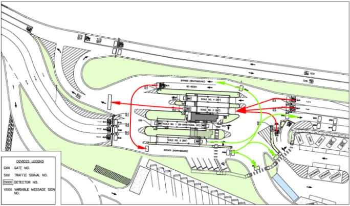
The naming convention identified each approach lane with an “L” with numbers 1 through 7 and each scale with an “S” with the numbers 1 through 4 representing each scale. In addition, “NBP” represents the northbound bypass lane and “SBP” represents the southbound bypass lane. Each vehicle movement was represented by combining the from and to movements. For example, the movement of a vehicle from Lane 2 to Scale 1 was represented as “L2_S1.”
Each traffic movement was identified on a site plan with green arrows representing inbound traffic movements and the red arrows representing outbound traffic movements as presented earlier in Figure 7. A layered file was used to visualize each combination of movements to identify conflicting movements.
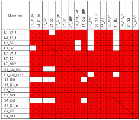
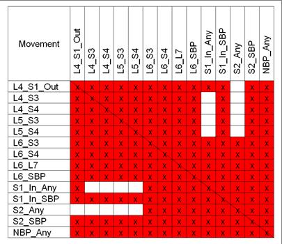
A matrix was created for each of the two conflict areas identified, the South Circulation Area south of the scale plaza (Table 1) and the North Circulation Area north of the scale plaza (Table 2). Each matrix includes all possible movements identified on each axis of the table. Conflicting movements were identified with red highlighted x’s; for example the movement of a vehicle from Lane 2 to Scale 1 (L2_S1) conflicts with a vehicle moving from Lane 7 to Scale 2 (L7_S2).
Critical to the success of the ATMS system was obtaining operator feedback to confirm both the possible movements and potential conflicts. Their knowledge assisted the design team in confirming site operations, site circulation and physical conditions to ensure that all anticipated vehicle interactions were captured. The site configuration, combined with the possible movements, introduced 206 possible conflicts, represented in Tables 1 and 2.
Efficiency
In addition to managing conflicts, efficiency was a critical component of the ATMS. System logic was required to address limited queuing capacity and facility capacity. In addition, it was recognized that the system needed to accommodate commercial and public customers with multiple destinations and interface points through the facility. The overall objective was to provide first-come, first-serve service. To maximize queue space, the site layout consists of multiple entry lanes. The ATMS logic was designed to address first-come, first served prioritization by alternating entry lanes and directing traffic to the next available scale. The logic was developed to provide an equivalent processing rate for each lane.
Certain areas of the facility, such as the recycle area, were identified as having capacity constraints. To ensure these areas did not create bottlenecks in the entire system, a need for prioritizing vehicles exiting these areas was identified. To create these priorities, the ATMS system calculates the area’s vehicle occupancy using in-pavement loop detectors at the entry and exit points. When a threshold is exceeded, priority can be assigned by the scale operator to vehicles leaving the area.
To further enhance operational efficiencies, one of the entry and exit lanes and scales is designated with signage for commercial users. These lanes use an automated weigh and payment system that does not need direct interaction with a scale operator. The integrated Paradigm payment system and ATMS work together at these designated lanes to expedite payment for commercial users and regulate their movements around the scale plaza. Although minimal interface with the scale operator is required, each interface point is provided with an intercom and pneumatic tubes back to the scale house. The use of dedicated lanes has greatly improved the service consistency and processing time for commercial vehicles as they are kept separate from the general public, who typically require direct interaction with the scale operator.
Reliability
Constrained by a facility that operates 24 hours a day, the system required an unprecedented level of reliability in order to maintain site safety and customer throughput. The reliability of the system was accomplished through use of redundant components and ability for the scale operator to manually override the automated system.
In order to meet the reliability requirements, numerous system fail-safes were incorporated into the ATMS design. Critical components of the ATMS included redundancies in the event of hardware or software failure. An example of the system redundancies includes the implementation of primary and backup system servers and touchscreen operator control consoles. ATMS peripheral devices and workstations are supplied with secondary power sources through battery-operated uninterruptable power supplies (UPS) rated for two hours of operation during a power outage and a diesel back-up generator system. The ATMS system was designed to operate even when individual components are out of service. Once any component is out of service, the logic is designed to continue operation with limited operator intervention. This includes taking advantage of the reversible scale. The scale operator can reverse the scale and the system will use the operational scales and route traffic to those scales that remain open. When any lane is closed or out of service, the ATMS logic is capable of automatically redistributing the traffic around the scale house to available destinations.
All peripheral devices also include a manual override function on the ATMS interface which allows a scale operator to disengage automated control during upset scenarios or emergencies. A failsafe “All-Stop” feature is also built into the system to halt automatic control during emergencies. This feature was intended to serve as a panic button that is provided as a large and visible button on the scale operator’s main ATMS control interface screen.
Functional Requirements
To satisfy all of the design requirements, functional specifications were developed which served as a guiding framework for the anticipated ATMS operations. Through several iterations of development with input from the owner, the specifications identified the system input, customer interface and controller equipment requirements.
System Inputs
The primary input required for the system is vehicle detection. In most cases this required installation of in-pavement induction loops that are typical for traffic signal installations. The scales also provided vehicle presence detection; in this case a minimum weight threshold was used to differentiate vehicles from pedestrians that may be walking across the scale. For safety, infrared photo-sensors were also implemented at gate locations where downstream loops were not installed. Photo-sensors would reverse the gate barrier from lowering when obstructed.
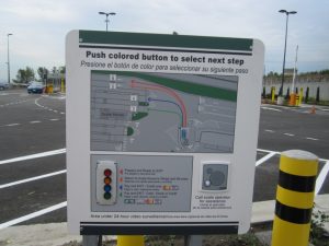
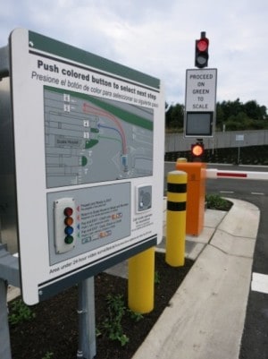
The recycle area exit lane, required input from the customer based on their need to dispose of additional material or exit the facility. This required a custom user interface keypad, as shown on Figure 8 with options on returning to the scale, exiting or paying by credit card. Recycle area customers receive some verbal direction on how to use the interface keypad from the scale operator on their way in but bilingual signage, a travel option diagram and an intercom were also provided at the interface. In the event that the customer arrives at the recycle area exit lane and does not provide any input, the scale operator will also be automatically notified to redirect the driver to the scale plaza’s outbound scale for further direct assistance from scale house staff.
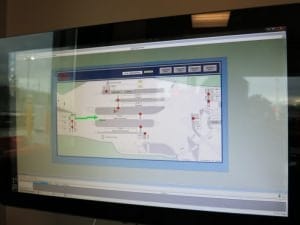
Using a “transaction complete” input signal from the County’s cashiering system, by default the ATMS automatically processes customers through the scale plaza with options to manually initiate movements under certain conditions. A touchscreen monitor allows the scale operators to manually input these movements when necessary. Figure 9 shows the ATMS touchscreen interface.
Customer Interface
There are two basic components required for the ATMS system to control traffic entering the site when and where the customer should go. A red or green traffic indication serves the primary purpose of identifying when to proceed. As an added safety feature, primarily to ensure only one vehicle proceeds at a time, barrier gates are also included. To provide the efficiencies described earlier, variable lane designation signs are also used. Each lane is designated using static signage. When a vehicle is released from any lane holding point, the variable component of the sign displays a scale (or lane) number directing the customer to an available scale.
Controller Equipment
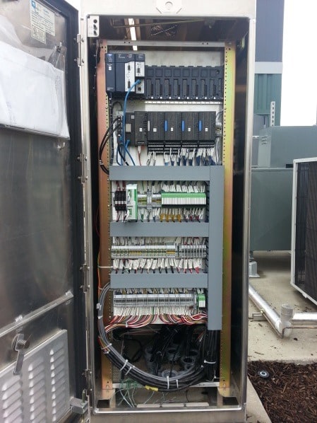
The programmable logic controller (PLC) is the central nervous system of the ATMS, where all of the system logic is stored. All of the functional requirements are programmed into the PLC including the allowable movements, conflicting movements and prioritization. The PLC manages the system inputs and outputs to control the ATMS, providing a safe, reliable and efficient system. The PLC is housed in a weatherproof cabinet that also houses electronics for field devices. Due to the large quantity of electronics and field connections and distances involved, two remote cabinets were also designed as part of the ATMS to receive additional system inputs and outputs. All three cabinets work together to manage the controlling logic of the ATMS system. Figure 10 illustrates the internal components of the PLC cabinet.
ATMS Commissioning
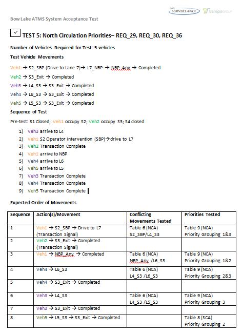
In addition to providing a highly reliable system, the ATMS design team was also challenged with validating the complex ATMS movement permutations using a rigorous set of system acceptance testing procedures. Once the ATMS system’s logic was developed, the design team executed a series of computer simulation tests as an initial means of system testing and validation. Vehicle movements were virtually simulated through the PLC’s software and closely monitored to identify anomalies with the intended system function. The computer simulation helped to significantly reduce the time necessary for field testing but was never intended to replace real-life scenario testing. The design team recognized that driver behavior is difficult to replicate in a virtual environment and prepared a series of real-life test scenarios. Test drivers were assigned a circulation route and order of arrival in a controlled environment. Through the live tests, external factors such as reaction time, driver expectancy, and human error were introduced and often resulted in additional software adjustments. Figure 11 provides an example of a real-life testing procedure that was implemented as part of the system acceptance tests.
A series of 18 real-life test scenarios were used to test the combination of possible conflict points and system rules. Over the course of three days, the live tests were staged and often required multiple trials in order to test the desired system interactions and outcomes. The system developers orchestrated the test procedures from the scale house, providing directions to drivers using two-way radios. The design team acknowledged the importance of conducting a comprehensive test procedure since public safety would be directly impacted by the test results. As an added precaution, the soft opening of the ATMS system and transition from the old to new scale house occurred during a night shift when traffic volumes are typically lower. Representatives from the owner, contractor, and design team were present to monitor system behavior. The entire team recognized that post-deployment system reliability was of paramount importance since the ATMS is a 24-hour operation with limited opportunities for major closures to make system adjustments. The first few days of system launch confirmed that all the critical movements and conflict point regulation performed as anticipated through testing. Minor post-system startup adjustments were made in the subsequent weeks to fine-tune the overall system efficiency. More impactful system adjustments are commonly implemented during the weekends when the site closes for eight-hour durations so as to not impact the safety of the public and ensure that revisions are tested in a controlled environment first.
Lessons Learned
The custom ATMS solution for the Bow Lake facility required input from several stakeholders and some faith in a conceptual plan that needed to work from day one. There were several important takeaways that should be applied to future ATMS solutions. At the Bow Lake Recycling and Transfer Station, new technologies and automation have solved a complex traffic circulation problem that was created by geographical and topographical constraints. As with all new technologies, it is not uncommon for there to be a burn-in period for site operators. The success of this project is highly attributed to the operational input and feedback provided by scale operators throughout the project lifecycle. Early in the planning and design process, it was evident that the input from King County’s scale operators would be invaluable. From their day-to-day experience and intimate knowledge of the site logistics, the ATMS team relied on their expertise to provide education on the operational constraints. This feedback was obtained through stakeholder workshops and working group sessions. During system development, the scale operators were also invited to test the beta version of the ATMS software and provide feedback on ways to improve and streamline processes. This synergistic working relationship with the scale operators resulted in an ATMS system that met the operational needs and smoothed out their learning curve as they were able to gain first-hand experience with the system at the design level.
Another important take-away from the Bow Lake ATMS design is to phase the specification and procurement of system hardware as close to the final implementation as reasonable, without impacting the project schedule. ATMS systems rely heavily on the capabilities of the technology and are often constrained by the physical limitations of hardware. Recognizing that an ATMS takes time to plan and design, technological advancements can result in a more robust and capable system when the latest hardware is implemented. Specifying and procuring hardware as close to final system launch as feasible will ensure that the end user benefits from the most capable hardware available at the time of deployment.
Related to project scheduling, our team also learned that close collaboration with the various construction contractors and civil project managers was important to the success of the project. As part of the Bow Lake implementation, the system integration and system acceptance testing was originally phased as a single task in the project schedule that did not overlap with any other construction activities in the scale plaza. Due to the dynamics of an evolving construction schedule and equipment lead-times, there was a need to work closely with the contractor to stage the system acceptance testing in the order that work was completed in order to remain on schedule. The entire team adopted a methodical approach to stage the testing separately for the recycling areas as well as north and south circulation areas to achieve a common goal of a timely project completion. With any new system and new operation, effective training is also the key to success and public acceptance. The Bow Lake ATMS succeeded in this area by providing the scale operators with a chance to inquire, provide feedback and contribute to the design throughout the project. The post-deployment training provided the operators with a system that had already been introduced to them and merely provided further details on the nuts and bolts of the detailed functionality. For the day-to-day operations and common features, the ATMS team provided two weeks of coaching for scale operators at the launch of the system. ATMS coaches provided a supervisory level of support to assist in ATMS operations as and when needed. Observations from the design team showed that this approach was effective in familiarizing the operators with the ATMS functions.
Even after the deployment and inauguration of the ATMS, the design team continues to learn important lessons. Because the Bow Lake facility is constrained by a 24-hour operation, there are few opportunities to implement hardware and software adjustments. However, the design team still recognizes the importance of implementing system changes in an offline-controlled environment so as not to impact the customer experience. The Bow Lake ATMS design team used a database to track all the required system adjustments and implemented all adjustments during a single weekend night closure, minimizing the frequency of system changes. Scheduling the adjustments at one time also allows all the adjustments to be tested at the same time in a controlled environment.
Karl Hufnagel is a Managing Engineer for Brown and Caldwell (Seattle, WA). He has managed large multi-discipline consultant teams in planning and designing complex solid waste facility projects since 1990. Karl managed the consultant team for the Bow Lake project and can be reached at (206) 749-2254 or e-mail [email protected].
Daniel Lai is an ITS Technical Manager for The Transpo Group (Kirkland, WA). He provided IT design for the Bow Lake ATMS system and can be reached at (425) 821-3665 or e-mail [email protected].
Garth Merrill is a Senior Transportation Engineer for The Transpo Group (Kirkland, WA). He helped plan the Bow Lake ATMS system and can be reached via e-mail at [email protected].
Tom Creegan is a Project Manager for the Solid Waste Division (SWD) of King County, WA. He is the project manager for the Bow Lake project and works closely with SWD operations, maintenance, engineering and planning staff to implement complex capital projects. He can be reached at (206) 477-5218 or e-mail [email protected].