Trucks
Third of Four Parts
Troubleshooting PTO Installation: Working Through the Bugs
Troubleshooting is a bit of an art and requires patience, specific product knowledge and good tools. If the PTO is not working as planned, simply step back and review the problem.
Mikel Janitz
This article is third in a series to help owners and end users plan the selection, installation and maintenance of vehicles equipped with power take-offs, extended shafts and hydraulic equipment related to mobile power. These articles cover the important and oftentimes forgotten topics mechanics need to be familiar with in order to get the most out of their power take-off (PTO).
Troubleshooting a PTO’s performance, or that of any other mobile power system, requires focus, planning and system knowledge; it is essential to keep that in mind as you approach the process. The two main troubleshooting areas are mechanical and electrical. The mechanical aspect has a few key areas of concern. Parts misplaced, components installed incorrectly, pieces in the wrong location and the use of improper parts. Electrical issues may include wrong or omitted parts, bad connections and/or poor grounding. Typically, there should not be any new parts left in the box or on the shop floor after the installation is completed and it is vital that the installer reads the instructions. One last major area deals with hydraulics and pneumatics and their relationship to electrical and mechanical functionality; these areas are touched on last. Remember to contact your distributor or call the PTO manufacturer to help with questions or troubleshoot if you need any assistance.
Where Do You Need to Start?
Focus on the mechanical and electrical aspect as they relate to and interact with the hydraulics and pneumatics circuits—essentially look at the system as a whole (see Figure 1). Study the system drawings or schematics and think through the system in order to decide on the best course of action. Make a plan and work it. Although it may seem obvious, make sure the vehicle engine is off and the equipment has had time to cool down before working around or under any vehicle. Working near rotating parts is extremely dangerous so be sure to use safe practices before beginning any work underneath the vehicle. Chock the wheels, remove the keys and be sure to put them in a safe place before applying lockout tags. Adhere to all safety warnings and precautions.
Mechanical
The first course of action is to study the system from start to finish. This works for mechanical, electrical or hydraulic debugging: a technique known as the divide and conquer method. First, focus on the mechanical side. Identify what is not working; for example, is the auxiliary equipment not rotating, not building pressure, leaking or is there simply just no flow? Start at the end of the system and work your way back toward the PTO. You may find that the problem is not even with the PTO to begin with. Look for something or anything that could be missing. Do the splines match? Are the splines engaged? Check to see if the woodruff key is missing from the output shaft. Are all the fasteners in place and tight? Verify that the extend shaft is installed in the housing. If it is a cable shift, confirm that the shift lever moves enough to properly engage the gears. If it is an electric shift, make sure the wires are connected. If it is air shift, confirm that there is a minimum of 65 psi of air pressure. Determine if the input gear is meshing with the transmission gear. Most PTOs have an indicator light mounted on a bracket in the cab and be sure to check to make sure it is connected and functional. If all of the PTO mechanical components are accounted for and properly installed, then is time to focus on the electrical side (see Figure 2).
Electrical
Electrical troubleshooting follows the same divide and conquer method. Again, make sure the engine is off and there are no rotating components. Start at the furthest end of the system and check electrical connections. Work your way back toward the PTO. Are components showing any signs of cracks or defects from installation? Is there anything leaking? If bad parts are discovered, replace them with new parts from the manufacturer. Do not substitute used parts. That practice is problematic and extremely difficult to ensure reliability. Next, trace the wire routing and remove or fix any kinks or pinched wires because pinched wires may cause grounding. Make sure wires do not touch the exhaust pipes. Wires that are too close to a heat source can melt and ground out components. Also, inspect each connection to ensure there is adequate contact. Use a continuity meter to verify routings and ground issues (see Figure 3).
If wires were crimped, make sure the insulation on the wire is removed and the terminal is connected firmly to bare wire. Poor connections can become hot spots later and are more susceptible to corrosion. Step back and take a minute to review the system and the schematic. Verify you have all switches, sensors and other electrical parts in place. Confirm they are secure in their location and check to see if the wires are crossed. Verify connections are not loose or disconnected altogether. Omitting parts, poor connections, jumping wires and using inferior substitutes will reduce your PTO performance. You will then find yourself back under the vehicle fixing what you should have done right the first time. Another important point to mention is PTO integration with the engine control module (ECM). Vehicles are becoming more sophisticated and it is vital the PTO is properly “plugged in” to the vehicle. Check the connection and wire routing and as always, be sure to review the supplied schematic that comes with the PTO (see Figure 4).
Hydraulic and Pneumatic System
It is extremely important to review the hydraulic and pneumatic system layout and diagram. Troubleshooting their circuitry, fittings, line orientation and their interaction with the mechanical and electrical system is essential to trouble-free operation. Again, use the divide and conquer technique. Isolate components and test where possible, one at a time. Verify proper fittings and hoses are used and look for pinched or restricted hose lines. Use the correct size of hose for the application. Hose routing is important; they must be secure and kept away from any/all heat sources. If you use zip ties, do not over tighten them because that can restrict flow in flexible lines as well. Keep them as straight as possible, and when routing requires bending, create a large radius.
Hydraulic systems require an adequate supply of fluid so be sure you have added enough fluid to fill the system and replenish any fluids that may have been spilled during installation. Make sure inlet lines are not crossed with outlet ports and vice versa and check the hydraulic/ pneumatic schematic. Verify connections are tight and not leaking and do not use Teflon tape with National Pipe Thread (NPT) fittings; remove any tape if found. Tape always seems to find its way into the fluid and can disrupt flow while causing damage to internal parts (see Figure 5).
Troubleshooting as an Art
Troubleshooting is a bit of an art and requires patience, specific product knowledge and good tools. If the PTO is not working as planned, simply step back and review the problem. Think about the mechanical, electrical and/or hydraulic and pneumatic features. Look around for extra parts on the floor or in the box. Divide and conquer to isolate parts to better evaluate their performance. Test and verify functionality whenever possible and use continuity meters, volt meters and gauges to quantify readings; you cannot just assume anything. Swap component parts with factory parts to identify bad parts and do not use old parts just to save money because it will cost you more money in the long run. The optimum PTO can be specified. The installation can be exacting; unfortunately, the unexpected happens and troubleshooting performance is sometimes required to get the job done right.
Mikel Janitz is the Manager of Engineering for Muncie Power Products (Muncie, IN), a global leader in power take-offs and a worldwide organization dedicated to solving the vocational industry’s mobile power issues. Mikel graduated from Oklahoma State University with a BS and MS in Engineering and Engineering Management. He can be reached at [email protected] or visit www.munciepower.com.
The final article in this series covers critical PTO maintenance topics.
Figure 1
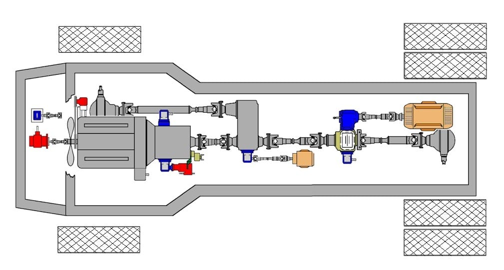
A top down section view. It shows multiples examples of PTO applications on a vehicle with mobile power needs.
Figure 2
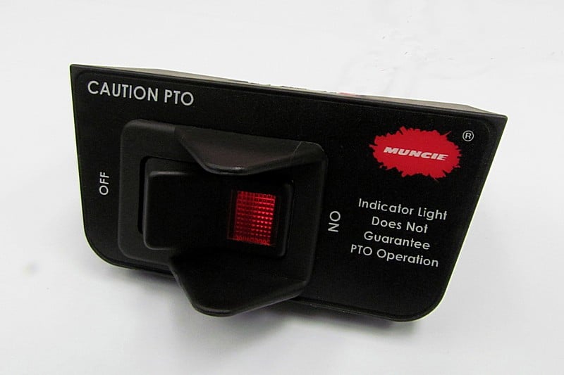
An example of an indicator switch. This is an under-the-dash PTO rocker switch with the indicator light illuminating.
Figure 3
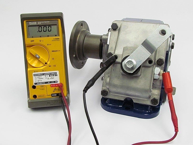
A typical test set up with a volt meter attached to the PTO. Remember to use a calibrated meter to ensure the most accurate results.
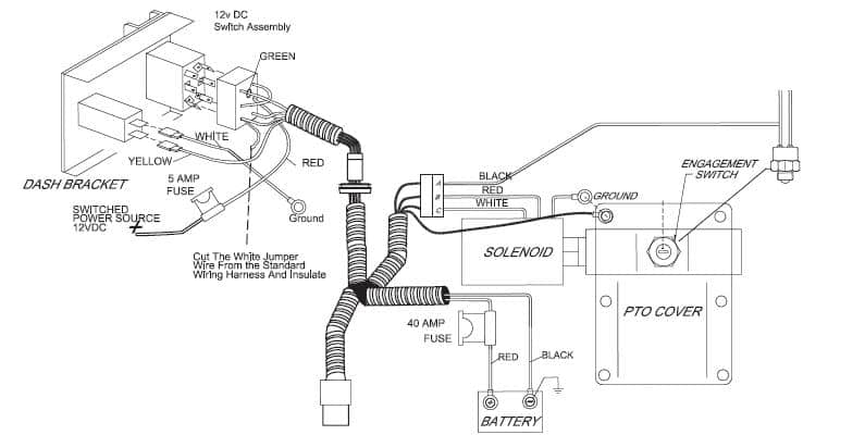
Figure 4

This is an electrical wiring depiction. Electrical wire installation and troubleshooting can be simplified by following and using the supplied schematic. These are typically found in the PTO owner’s manual.
Figure 5
Here is a hydraulic system depiction. Hydraulics systems can be very complicated to install. This is a simplified depiction with clearly identified parts to help with the installation and troubleshooting.
Images courtesy of Muncie Power Products.