Nathan P. Mayer, Manuel J. Hernandez, Abdul Mulla Saleh, S. Steven Carl and Ralph Calistri
Chapter 62-701.500 of the Florida Administrative Code (F.A.C.) requires that existing leachate collection systems (LCS) “be water pressure cleaned or inspected by video recording at the time of permit renewal.” Additionally, operations permits with the Florida Department of Environmental Protection (FDEP) require an annual demonstration that the LCS is functioning and operating properly as designed. To fulfill regulatory and permit requirements, landfill operators use water jetting and/or video inspection to confirm that the LCS is functioning and operating as designed. Annual inspections have shown that landfills, including municipal solid waste (MSW) landfills, ash monofills and commingled MSW/ash landfills, are experiencing biogeochemical clogging in their LCS, creating regulatory compliance and operational issues for landfill owners.
For multiple landfill facilities in Florida, CDM Smith evaluated the conditions of the LCS, conducted precipitate mineralogy and chemical composition analysis to determine how and why precipitate is forming, outlined the pipe cleaning technologies available, provided pilot testing for the proposed technologies, and determined the technology best suited for the particular system. This article discusses the reasons for precipitate formation, the cleaning technologies employed, and operational changes that may help to prevent formations of precipitate.
Clogging Mechanisms
A landfill LCS can consist of aggregates, geocomposites, collection trenches, pipes, cleanouts, pumps, lift stations, storage tanks, wet wells, etc. Clogging of any portion of the system can lead to higher hydraulic heads within the landfill, increasing the potential for leachate outbreaks over containment berms and/or leakage through the liner. Studies have shown that clogging is widespread and its occurrence can attributed to several factors including sedimentation and deposition of fines, biological clogging, and chemical and/or biogeochemical precipitation. Typically, clogging is caused by the formation of biofilms and insoluble mineral deposits that fill the void spaces within the drainage layer and/or perforated collection pipes within the LCS.
Biogeochemical clogging can be attributed to thermodynamically favored precipitate formation influenced by supersaturated conditions based on saturation indices of calcium, sulfide, iron and other species. Furthermore, clogging may also be attributed to the presence of large numbers of microorganisms in landfill leachate. Sulfate and iron reducing bacteria (SRB/IRB) play a major role in forming biologically induced calcium carbonate (CaCO3) precipitate in a reduced environment. The decomposition of waste involves the fermentation of primary substrates to sugars and alcohols. Volatile fatty acids (VFAs), primarily acetic acid, are converted to substrate by SRB/IRB, which is then consumed by methanogenic bacteria to produce carbon dioxide and methane. Consumption of VFAs and hydrogen causes the local pH to rise, increasing the total carbonate in the system. In the presence of calcium, these reactions allow for and accelerate the chemical precipitation of calcium carbonate, the dominant inorganic species in the “slimes” found in LCS. These “slimes” are waste products from bacteria metabolism, which provide a protective environment and nutrients for bacterial growth and nucleation.
CH3COO– + SO42- + H+ → H2S + 2HCO3ˉ
CH3COO– + 8Fe3+ + 2H2O → 2CO2 + H2S + 8Fe2+ +7H+
Ca2+ + HCO3ˉ → CaCO3(s) + H+
Fe2+ + H2S → FeS(s) + 2H+
Characteristics of Leachate and Precipitate
Leachate Analyses
The chemical composition of leachate is influenced by a variety of factors including waste characteristics and age, the quantity of liquid that has percolated through the landfill, the biological activity of the landfill, and the status of chemical complexation and solubility reactions. In addition to MSW landfills, many landfills accept residuals from combustion processes, and from water and wastewater treatment facilities. Collectively, the relative amounts of MSW, process residues, and other waste materials disposed of in a landfill impact the short-term and long-term composition of leachate and the biogeochemical reactions that result from waste degradation during the life of the landfill.
To gain a better understanding, leachate chemical composition and precipitate mineralogy analyses were conducted at several landfill facilities in South Florida (both ash monofill and combined ash/MSW) to determine how and why the precipitate is forming. Results showed high concentrations of calcium, chlorides, and sodium. Moderate concentrations of sulfate, organic carbon, and silica were also present. Similar studies show that leachates from ash monofills are dominated by high concentrations of dissolved calcium (see Figure 1).
Geochemical Modeling
Geochemical modeling was performed using the Reaction Module (REACT) of The Geochemist’s Workbench®, Release 6.0 (GWB) to simulate the reactions that might occur in the leachate environment. The model simulation begins by calculating the initial equilibrium state of the geochemical system that contains the aqueous fluid. The model then calculates the equilibrium distribution of aqueous species in the fluid and the fluid saturation state to predict possible reactions and precipitate formations based on field and laboratory test results as input parameters.
The results of the analysis conducted on leachate from a combined ash/MSW landfill showed the predominant precipitates are calcite (calcium carbonate, CaCO3) and dolomite (calcium magnesium carbonate, CaMg(CO3)2) with trace amounts of hydroxyapatite (a complex of phosphate and calcium, Ca5(PO4)3(OH)), quartz (SiO4), and siderite (FeCO3). Similarly, the results of the analysis conducted on leachate from an ash monofill showed the predominant precipitate as calcite with trace amounts of hydroxyapatite and quartz.
Precipitate Mineralogy
In addition to liquid phase testing and geochemical modeling, precipitate mineralogy was also performed on samples collected from the LCS. Samples were analyzed using X-Ray Diffraction (XRD) to identify the dominant minerals present in the precipitate material. Results indicated that calcium carbonate was the predominant precipitate with traces of both brushite (Ca(HPO4)*2H2O) and gypsum (Ca(SO4)*2H2O) present. Finding calcium carbonate in these samples is consistent with the geochemical modeling results and the results found in similar studies (see Figure 2, Figure 3).
Cleaning Technologies
After conducting precipitate mineralogy and chemical composition analysis to determine how and why the precipitate is forming, CDM Smith was tasked with outlining the pipe cleaning technologies available and setting up pilot testing. The following methods for removing precipitate material were evaluated.
Mechanical Methods
Mechanical methods include high-pressure water jetting and milling cutters. Various nozzles and cutters can be used on the end of high-pressure hoses to remove precipitates and flush debris from pipes.
High-Pressure Water Jetting
Removal of the precipitate material requires high pressures, typically between 4,000 and 10,000 psi. Equally distributed, high-pressure water jetting is used to distribute the pressure along the surface of the precipitate without creating a point pressure on the inside wall of the pipe itself. This method reduces the likelihood of damaging the pipe. Penetrating (point-focus), flushing (equally distributed), and rotating nozzles have been used successfully at other landfills to remove precipitate formations. A maximum applied pressure of 7,500 psi is typically established to protect the integrity of LCS pipes (see Figure 4, Figure 5).
The pressure and volume of water used when jetting can have varying results on the removal of precipitate in a pipe. Increasing the pressure tends to dislodge precipitate in the pipe, whereas increasing the volume of water assists with moving the dislodged material through the pipe, downstream for removal. A combination of high-pressure and high-volume water jetting can be used to clean the LCS.
Cutters and Milling Machines
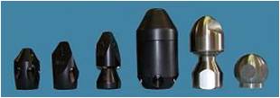
Cutters and milling machines are also used to remove precipitates from pipes. This equipment is typically attached to the jetting hose and the water pressure from the jetting equipment drives the cutter or milling machine. This option requires the use of jets to remove the material that is loosened by the milling machine. Milling cutters are designed to align themselves within the pipe; however they can potentially cause damage to the pipe walls, especially near transitions, changes in pipe material, and welds within HDPE piping. Additionally, consideration must be given to explosion potential, due to the presence of landfill gas (see Figure 6).
Chemical Treatment
Chemical treatment includes recirculation and/or resurgance of a chemical, typically an acid blended with specialty chemicals to enhance activity, within a pipe segment. The chemical is allowed to sit in the pipe for a period of time, depending on the chemical used, to provide adequate contact time between the precipitate material and the dissolving chemical. Large quantities of chemical may be required, depending on the configuration of the LCS.
Cleaning Demonstrations
Cleaning demonstrations were used to evaluate both the effectiveness and cost of the cleaning technologies discussed above. Each technology was given three days to clean a specified section of LCS piping. Daily video inspections were used to assess the progress of each technology and confirm that they were not negatively affecting the LCS. Due to the risks involved with properly sizing the milling cutter, it was recommended that this technology be used as a last possible option.
Both chemical cleaning and high-pressure water jetting were successful at removing precipitate from the demonstration areas. High-pressure water jetting was successful at removing several large, intact pieces of precipitate from the LCS. However, debris buildup at pipe transitions and intersections was a constant issue. Transitions made it difficult to flush dislodged debris. As one piece of precipitate was flushed, another followed, creating a problem with continuous removal of fractured precipitate. The removal of heavy precipitate requires a slow, staged cleaning approach, significantly increasing the time and cost of this cleaning technology. High-pressure water jetting also requires access points for removal of larger dislodged precipitate material, and most LCS designs do not always allow for this.
Chemical cleaning was successful at removing most of the precipitate formation, especially in the lower lengths of the LCS. Video inspections confirmed that this technology was successful at removing heavy buildup and restoring flow in areas that were clogged and/or appeared stagnant at the beginning of the cleaning demonstration.
Based on the results of the demonstration, the cost and effectiveness of the two technologies evaluated were compared. This evaluation showed that high-pressure water jetting is capable of cleaning up to 1,500 feet of pipe per week, depending on how heavily deposited with precipitate it is and how easily the dislodged precipitate can be removed from the system. Chemical cleaning is capable of cleaning over 2,000 feet of pipe per week. This equates to $20 to $40 per foot of cleaned pipe.
Conclusion
Based on the results of the demonstration and an evaluation of cost, chemical cleaning was determined to be the best technology for removing heavy precipitate buildup, especially in the lower lengths of the LCS, pipe sections with multiple access points, and non-perforated piping. The chemical cleaning technology was provided by Progressive Environmental Services (PES) (Norfolk, VA). PES’s proprietary products are designed to penetrate, disperse, dissolve, and remove scaling and corrosion by-products, biofilm and all other existing microbial activity.
Part 2 of this article will discuss the full-scale chemical cleaning projects, including the methods employed and results of the cleaning.
Nathan P. Mayer, P.E., is a Project Manager for CDM Smith (West Palm Beach, FL). He can be reached at (561) 689-3336 or via e-mail at [email protected].
Manuel J. Hernandez, P.E., BCEE, is a Senior Project Manager for CDM Smith (West Palm Beach, FL). He can be reached at (561) 689-3336 or via e-mail at [email protected].
Abdul Mulla Saleh, Ph.D., P.E., BCEE, is the Solid Waste Practice Leader for CDM Smith (Tampa, FL). He can be reached at (813) 281-2900 or via e-mail at [email protected].
S. Steven Carl is President of Progressive Environmental Services (Portsmouth, VA). He can be reached at (757) 606-1840, via e-mail at[email protected]or visit the Web site at www.progressive.us.com.
Ralph Calistri is an Officer for Florida Jetclean (Tampa, FL). He can be reached at (800) 226-8013 or via e-mail at [email protected].
References
- Cooke, A.J., 2000, “Modeling Clogging of Landfill Drainage Systems”, In Proceedings of the 6th Environmental Engineering Specialty Conference of CSCE & 2nd Spring Conference of the Geoenvironmental Division of Canada Geotechnical Society, London, Ontario, June 2000, pp. 74-80.
- Levine, A.D, 2005, “Assessment of Biogeochemical Deposits in Landfill Leachate Drainage Systems”, Florida Center for Solid and Hazardous Waste Management, Report #0332006-05.
- Maliva, R.G., 2000, “Unusual Calcite Stromatolites and pisoids from a Landfill Leachate Collection System”, Journal of Geology, Vol. 28, No. 10, pp. 931-934.
- Manning, D.A.C., 1999, “Leachate Mineral Reactions: Implications for Drainage System Stability and Clogging”, In Proceedings of the Seventh International Waste Management and Landfill Symposium, Sardinia, Italy, October 1999.
- Rittman, B.E., 1996. “Leachate Chemistry: Its Implication for Clogging”, In Proceedings of the North American Water Congress, Aneheim, California, June 1996.
- Saleh, A.R.M, 2006, “Assessment of Biogeochemical Deposits in Landfill Leachate Drainage Systems – Phase II”, University of South Florida Theses and Dissertations. Paper 2686.
Figure 1

Leachate parameters table.
Figure 2
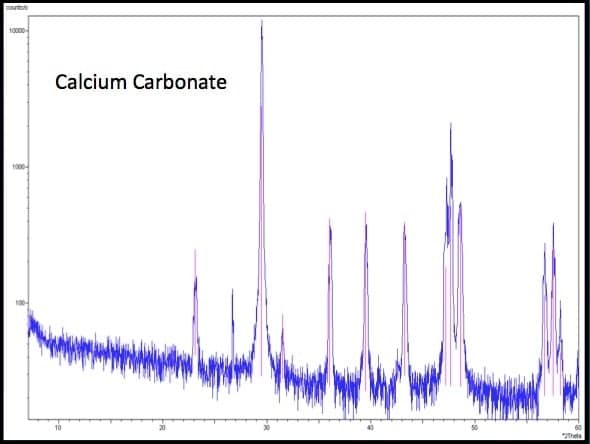
X-ray diffraction results – Calcium Carbonate.
Figure 3
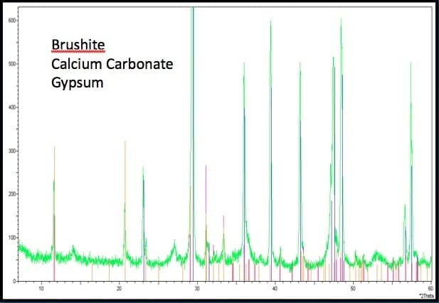
X-ray diffraction results – Brushite, Calcium Carbonate, Gypsum, etc.
Figures 4 and 5
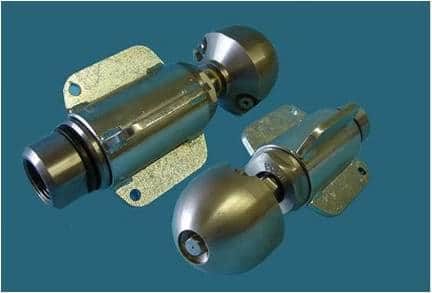
High-pressure water jetting nozzles.
Figure 6
Milling cutters.
Images courtesy of CDM Smith.