Complexity of landfills vary from site to site and issues related to conflicts among gas and liquids pipes, and final cover geosynthetics. The best way to resolve conflicts before the project goes to construction is to have a coordinated effort among parties involved in the design to discuss and find solutions to every conflict at the design stage.
By Ali Khatami, Ph.D., P.E., LEP, CGC
Landfills are complex systems with many pipes for liquids and landfill gas running in many different directions. Pipes carrying liquids may be leachate collection pipes, leachate force main, condensate lines, gas well liquids lines, leachate seeps lines, storm water down chutes, rainwater toe drain lines and leachate toe drain lines, to name a few. Pipes carrying liquids are normally for a specific purpose and some of these pipes have to be located at a certain location following gravity and have to have a certain slope and direction for the liquid to reach the intended designated point. Often, the landfill designers are different than the gas system designers for a specific landfill; and very often, there is no coordination among the two designer groups for a specific design/construction project. Inconsistencies in the two designs occur frequently that would have to be resolved in the field during construction at a high cost to the owner and causing delays in construction completion timeline.
In addition to the liquid and gas pipes conflicting design recommendations, conflicts with final cover geosynthetics have also been observed in design packages. This article suggests design considerations to help prevent conflicts in design packages prepared by more than one party.
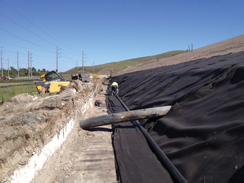
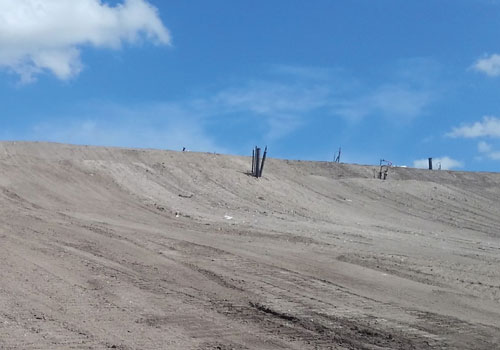
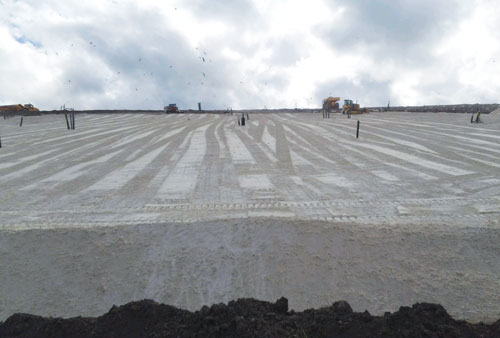
Photos courtesy of SCS Engineers
Final Cover Geosynthetics
Include the final cover layers in the gas design details where gas wells are installed near the landfill final surface. This inclusion will help the designer to specify proper heights for gas wells, proper depths for gas headers and lateral pipes, and proper heights for condensate sumps within the lined area of the landfill. Otherwise, locations of these elements may end up being in conflict with the location of various layers of the final cover system to be constructed later.
If flow control valves are located below the final cover near the perimeter of the landfill, design a vertical casing around the valve tall enough that future final cover can be booted to the vertical casing and access to the valve would be possible. Do not use corrugated material as casing because it would be difficult to place a geomembrane boot over corrugated casings. The designer should require sealing the void inside the casing pipe to prevent landfill gas release or oxygen intake through the void. If the control valve is located above the final cover, the designer should specify proper height for the casing pipe that access to the valve stay above the final cover surface.
Condensate sumps installed prior to construction of the final cover should be tall enough to accommodate construction of the final cover system around the condensate sump with sufficient space to boot the final cover geomembrane to the exterior walls of the condensate sump. Miscellaneous stub outs on the condensate sump should be designed in consideration of having enough space for the geomembrane boot in the future.
Pipes connected to a condensate sump (such as compressed air line, discharge force main, power conduits, etc.) should be positioned such that boots can be placed on each line at the penetration point of the pipe through the final cover geomembrane. Boots may not be placed on pipes clustered together. If boots are placed on a pipe cluster, the designer should require sealing the voids between the pipes within the boot to prevent landfill gas release or oxygen intake through the voids.
Always leave pipes exiting inside the liner boundary at the perimeter of the landfill at least 1 foot above the anchor trench shoulder. When the final cover is installed, it would be impossible to install a geomembrane boot over at the cover geomembrane penetration point of a pipe that is in contact with the bottom lining system geosynthetics over the anchor trench shoulder.
Rainwater Toe Drain System
Locating flow control valves near the landfill perimeter and within the lined area should be in consideration with the future location of a rainwater toe drain system at the toe of the slope that will be constructed when the final cover is constructed.
Large gas pipes located above the final cover geomembrane and crossing terraces on landfill side slopes may create conflict with the rainwater toe drain at the terrace. The designer should design terrace crossings such that future conflicts can be avoided.
Large gas pipes located above the final cover geomembrane and crossing an access road on the landfill slope may cause a conflict with a rainwater toe drain system above the final cover geomembrane running parallel to the access road at the toe of the slope next to the access road. The gas pipe running under pushes the rainwater toe drain pipe up, disturbing the flow line of the pipe. The gas pipe running above the rainwater toe drain pipe may disturb the flow line of the ditch above. The conflict may be avoided by locally increasing the thickness of the soil above the geocomposite drainage layer and rainwater toe drain system to leave adequate height for the gas pipe to cross through. This will locally impact the slope of the road, which can be handled by starting the rise and fall some distance, such as 50 ft., on either side of the gas pipe.
Storm Water Downchutes
Large gas pipes located above the final cover geomembrane may cause conflict with storm water downchute pipes that will be installed above the final cover geomembrane. Special depressions may have to be designed to place downchute pipes below gas pipes on the slope. Placing gas pipes above downchute pipes may cause problems with flow of condensate in the line.
Similarly, large gas pipes can potentially impact open downchutes. Open downchutes normally are designed in the form of a depression in the 2-foot thick soil layer above the cover system geosynthetics. The depression for the downchute reduces the thickness of the soil layer, preventing a large gas pipe to pass through under the downchute. The design should consider locally increasing the thickness of the soil layer to provide sufficient thickness between the bottom of the downchute and the final cover geosynthetics for the gas pipe to pass through. The flow lines of the terraces or tack-on swales draining to the downchute also need to be locally adjusted to accommodate flow of storm water toward the downchute.
Horizontal Gas Pipes
Sometimes horizontal gas collection pipes come out of the landfill side slopes and extend down the slope to a gas header or some other component of the gas system. If the pipe segment on the slope is going to be below the final cover geomembrane, then it must be placed deep enough in waste that it would not have any conflict with the final cover system components, such as leachate toe drain systems, terraces, access road ditches, etc. If the pipe segment is going to be above the final cover geomembrane, extension of the horizontal pipe connecting to the pipe segment on the slope will be designed such that the horizontal pipe can penetrate the final cover geomembrane and extend down the slope while located above the final cover geomembrane. Extension of the pipe on the slope above the final cover geomembrane should not cause any conflict with the final cover components, such as rainwater toe drains at terraces or at the toe of the slope next to the perimeter berm, downchute pipes, terrace or access road grades, etc. The elbow at the connection of the horizontal pipe to the pipe segment on the slope and above the cover geomembrane is very important because a geomembrane boot must be installed at the penetration point.
Tack-on Swales
If tack-on swales are used on the landfill slopes, large gas pipes on top of the final cover geomembrane may cause conflict with the flow line inside the tack-on swales. Large headers should cross tack-on swales at the high end point of adjacent swales to prevent flow problems in the swale. If tack-on swales are used, location of wells for drilling purposes should be chosen to be outside the tack-on swale structure.
Terrace or Access Road
If a gas header located above the final cover geomembrane and crossing a terrace or access road where the terrace or access road is sloping toward the landfill, condensate flow through the gas header may become an issue. Special depressions across the terrace or access road may need to be designed such that condensate can flow in the proper direction.
Large gas pipes located above the final cover geomembrane and crossing the access road on the landfill slope may cause road grade problems at the final surface. Specific depressions across the access road width may have to be designed for larger pipes to prevent grades problem at the finish surface.
Gas pipes crossing an access road on the landfill slope may cause conflict with a ditch adjacent to the access road at the final cover surface. Locations of gas pipes, either below or above the final cover geomembrane, should be designed in consideration of the final cover features that will exist in the crossing area in the future.
A Coordinated Effort
Complexity of landfills vary from site to site and issues related to conflicts among gas and liquids pipes, and pipes and final cover geosynthetics vary depending on the geometry and other landfill features involved at each location. The best way to resolve conflicts before the project goes to construction is to have a coordinated effort among parties involved in the design to discuss and find solutions to every conflict at the design stage, or, alternatively, have one party to design landfill and gas system features.
Ali Khatami, Ph.D., P.E. is Vice President of SCS Engineers (Long Beach, CA). He has more than 30 years of experience in design, permitting and construction of landfills. Dr. Khatami serves as the National Expert for Landfill Design, Construction Quality Assurance, and Elevated Temperature Landfills for SCS. He has extensive experience in various fields of engineering involved in design of landfills. Dr. Khatami has numerous technical publications and has been co-author on two books. He can be reached at [email protected] or visit www.scsengineers.com.