Joseph P. Curro, P.E., BCEE
Many landfills are required by various regulations to install active landfill gas extraction and control systems. The primary goal of a landfill gas extraction and control system is to safeguard the public by preventing the landfill gas from migrating across the property boundary of the landfill or being emitted from the surface of the landfill. While the collection and control systems are primarily installed as a way to control odors and to reduce methane and volatile organic compound emissions, they have also been used as alternative energy sources in nearby fuel using facilities. Such “direct use” facilities typically have installed boilers or other systems to use natural gas and/or fuel oil in heating or other process applications. These systems are fitted with burners that are dedicated to the type(s) of fuel being used. In most cases, these existing fuel burners can be converted to add landfill gas as a fuel (see Figure 1).
Landfill Gas Production
As a byproduct of waste decomposition, landfills produce a gas that is primarily compromised of methane which is classified as a medium BTU gas at 400 – 600 BTUs per cubic foot. In order to investigate possible reuse applications of the landfill gas, factors such as landfill gas generation rates and available users must first be determined. While electric generation is a valuable and viable choice, the best way to use this would be onsite generation. Some State and local utilities do offer power purchase agreements to encourage landfill gas based power generation, however a more economical way to reuse the landfill gas is in a direct fire combustion unit such as a boiler, process heater or other combustion equipment (see Figure 2).
In order to successfully use landfill gas in a boiler or process heater that is designed to burn natural gas and/or fuel oil, modifications to both the burner and the fuel supply train are needed. The heat value of a fuel refers to the amount of energy that is released during complete combustion of one mass unit of the fuel. The less inert elements that the gas contains, the greater its heat content will be. Since landfill gas’s heating value is largely dependent on the amount of methane present in the gas stream, it is important to know approximately how much methane is available. The typical methane concentration can be anywhere from 40 to 60 percent (equal to a heating value of about 400 – 600 BTU per cubic foot) with the rest a mix of carbon dioxide, oxygen and nitrogen. Conversely, natural gas has a heating value of 1,000 BTU per cubic foot, composed very nearly entirely of methane. This means that any modifications made to the burner and fuel train will have to be made to accommodate a higher gas flow rate to achieve the equivalent heating capacity. Engineering decisions must be made as to whether to retrofit an existing burner or replace it to handle the dual fuel capacity. Key information to make this decision is based on the amount of landfill gas available for the process, the design of the burner and the age of the systems and subsystems serving the burner.
Given a more widely available supply of landfill gas, a greater awareness of the value of this gas and an increased willingness of facilities to entertain its use in various processes and a greater availability of hardware and expertise needed to accomplish such a conversion, burner modifications to accommodate landfill gas firing are more routinely made. In conjunction with burner modifications, improved process controls of the air to fuel ratio, control of natural gas/oil/landfill gas ratios, and combustion product flows can be installed to ensure that the increased flow of landfill gas (required to meet the same BTU value of natural gas) can be accommodated across the burner and throughout the furnace and/or boiler system.
Although there exists a vast array of burner types and configurations, this discussion will be limited to the most commonly used industrial burner systems, i.e. nozzle mix and premix burners. Both nozzle mix and premix burner systems are commonly used in gas combustion and are frequently used in multi fuel applications such as natural gas/landfill gas, natural gas/landfill gas/fuel oil and fuel oil/landfill gas systems (see Figure 3).
Nozzle Mix Burners
Nozzle mix burners can operate within a wide range of fuel to air ratios, since nozzle mix burners do not mix the gas and air streams until after they enter the burner port, or nozzle. Up to the burner port, the air and gas streams are kept separated, in individually controlled streams. Excess air is introduced into the burner at the nozzle at the same time the fuel is introduced. Gaseous fuels are introduced into a nozzle mix burner through a series of ‘spuds’ which are located in a circular pattern around the burner block. Addition of another gaseous fuel, such as landfill gas, would require the installation of another set of alternating spuds. When the mixing is carried out in the burner head, the gas released into the combustion chamber already has the correct composition and air/fuel ratio. Thus, the combustion reaction is quick and the resulting flame is fully mixed with efficient use of the fuel and minimal excess air requirements and flame chilling (see Figure 4).
Nozzle mix burners have a higher turn down range (the ratio of the burner’s maximum BTUH firing capability to the burner’s minimum BTUH firing capability) than other burners because they only control the gas flow and can use preheated air. The process control of the nozzle mix burners is enhanced with a high turndown. If the load is smaller than the burner can turn down to, it cycles on and off. When the burner is off, the pressure or temperature can fall off. With high turndown, fluctuations in the temperature and pressure are reduced because the burner tracks the load down to the point where it shuts off only when the load is very low.
Premix Burners
Premix burners were one of the earliest types of high input, high stability burners. In premix burners all of the air and fuels are mixed before the point of ignition and flame development within the burner. Premixing increases the homogeneity of the fuel and air in the mixture which allow the amount of fuel burned to be increased. Premix burners use fuel with a mixing of forced air from an associated blower or compressor. There are two basic types of premix burners—open and sealed. Open premix burners use a steel or cast iron retention tip and sealed premix burners use a tunnel or multiport tip mounted into the furnace wall.
Premix burners provide greater control over the air and gas mix and produce higher temperature combustion products, however premix burners are limited in size, turndown range and stability. Sealed premix burners do not require secondary air whereas open premix burners need secondary air for cooling purposes. This helps to ensure the tip’s life is extended and that complete combustion is achieved.
When a premix burner is used, the control over the air and gas mix produces a high volume through the burner. This high volume creates a high velocity on the gas stream which, in turn, produces a short flame of bluish color, at high temperature and with a highly defined geometry. If not enough air is incorporated for complete combustion, a second zone of colorless flame is produced which creates a plume which surrounds the blue flame.
Each burner must have a means of fuel/air ratio control to ensure efficient operation. While electronic controls are available, the most used method is a cross connected ratio regular. This regular is designed to maintain a fuel outlet pressure that matches the combustion air pressure to the burners.
Fuel Trains
Arguably a far more important aspect of any fuel use project is the proper design and installation of a fuel ‘train’. A fuel train consists of various safety shutoff valves, flow regulating valves, manual isolation valves, vent valves, fuel/air ratio valves, pressure regulators and other components to ensure safe and efficient operation of the burner system. A project wherein an existing burner is to be converted to add landfill gas firing, an existing fuel gas train or trains would be in place. The first step in determining the reusability of an existing fuel gas train would be to investigate its age, condition and compliance with current codes. In a case where an existing fuel train is determined to be proper for a modified system, conversion would consist of the addition of a landfill gas fuel train that would serve a modified burner. Typically, fuel trains (of any type) are rack mounted, factory fabricated systems that incorporate appropriate subsystems and require only connection of landfill gas inlets and outlet piping, air inlet and outlet piping and control wiring. These rack mounted fuel trains are typically located adjacent to the existing fuel train(s) (see Figure 5).
In a case where it is determined that an existing fuel train is not proper to serve in parallel with a new landfill gas fuel train, a new, integrated, multi-fuel train can be installed. As described previously, this train would also be rack mounted, but it would encompass all elements required for safety and control of all fuels and combustion air. This type of train would also be factory fabricated and located adjacent to the burner, requiring only field connection of fuel piping, air piping and control wiring.
Fuel trains do not differ significantly between service for nozzle mix or premix burners. The most significant difference would be that natural gas and landfill gas may be blended in the piping prior to the entrance of the blended fuel to the fuel train. Although this is a common practice, the variance of natural gas to landfill gas ratios is a more complicated operation.
Fuel Blending
At some point in the fuel delivery to either type of burner, natural gas, and/or oil, and landfill gas must be blended for combustion. Although these burner types can successfully operate using 100 percent landfill gas as a fuel, it is always advisable to maintain a base load of an uninterruptible fuel supply (such as natural gas or oil) for flame stabilization and/or fast response to changes. Since many factors can influence the supply of landfill gas to a burner, the ability of the burner to maintain a stable flame and to modulate to full fuel firing (exclusive of landfill gas) rate is essential to maintain proper process operation. Since the fuel is always flowing, the lag time to bring a natural gas or oil supply on line is minimized and process interruptions are rare (see Figure 6).
Combustion Products Flow Rates
Although landfill gas is a viable and frequently used substitute or supplement for commercially available fuels, it must be realized that significant differences exist. While natural gas is composed of virtually 100 percent methane, landfill gas consists of 40 to 60 percent methane with the balance of the gas comprised generally of carbon dioxide. When landfill gas is used as a fuel, a much higher volumetric flow rate must be supplied to the burner for a given heat input. Taking these factors into consideration, an equivalent heat flow of landfill gas would require at least double the volumetric flow of landfill gas. As the landfill gas passes through the burner and into the process furnace, the carbon dioxide is heated to the process temperature and greatly expanded. In addition to the burner conversion, the engineer or process designer must take these flows into consideration in determining the applicability or suitability of the overall system to accommodate landfill gas and its resultant products of combustion.
Safety
As with any fuel burning process equipment, safety is of the highest concern. It has been shown here that many types of existing fuel burners can be converted and modified for the addition of landfill gas firing. However, it is the duty and responsibility of the engineer or designer of the fuel burning equipment and the process to address the safety issues and to follow all codes and standards of practice. This article is meant solely to introduce qualified technical experts to the generalities of burner conversion. Many factors not described here can have a profound effect on the safety of systems, possibly leading to personnel injury or death and extensive equipment damage. Only qualified experts should attempt such conversions.
Conclusions
A vast array of burner designs exist in today’s industrial environment. While many of these burners are relatively new and of modern design, it must be realized that not all can be converted or modified to fire landfill gas. In addition to the process of converting burners to fire landfill gas, consideration must be given to safety, fuel/air mixing, flame development and flows of combustion products through the process system. When taking all things into consideration, following proper codes and ordinances, and using industry accepted design practices, a successful and profitable landfill gas combustion product can result.
Joseph Curro is a principal environmental engineer, senior solid waste engineer, senior combustion systems engineer and the landfill gas discipline leader with CDM Smith (Cambridge, MA). He has more than 40 years of experience in solid waste and combustion projects, concentrating on solid waste and landfill gas combustion, landfill gas extraction and control, and field operations. Joseph has served as the lead design engineer for numerous landfill gas extraction, cleanup, compression, flaring, beneficial use and transmission systems. He can be reached at (617) 452-6255 or via e-mail at [email protected].
Figure 1
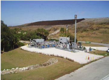
Typical landfill and landfill gas conditioning, cleaning and delivery system.
Photo courtesy of CDM Smith.
Figure 2
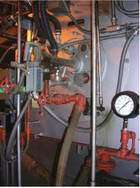
Natural gas/ No. 2 oil fired industrial burner.
Figure 3

Landfill gas/Natural gas fired burner.
Figure 4
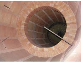
Fireside view of a nozzle mix burner and combustion chamber.
Figure 5
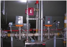
Blended gas fuel train.
Figure 6
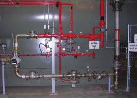
Landfill gas/Natural gas blending station.
Photos courtesy of J. Curro; CDM Smith.