Creating more disposal capacity while reducing impacts.
By Don Hullings, Bodhi Piedmont-Fleischmann and Kirstie Shurie
Mechanically stabilized earth (MSE) berms are a practical technique for expanding capacity in existing landfills. Over the past several years, the authors have been involved in designing and permitting several landfill expansion projects incorporating MSE berms. Each facility was unique, but they all required an evaluation of economics, design considerations and other landfill-specific issues. In the end, each MSE berm significantly enhanced the facility’s total disposal capacity and site life while resulting in several additional benefits for the sites.
Need for Landfill Space Persists
The ideal goal of an environmentally efficient waste management system is to eliminate the need to send waste to a landfill. However, this goal cannot be achieved with our existing waste systems and collection/separation/recycling infrastructure. Landfill facilities continue, for the time being, to be necessary to manage the portion of waste materials that cannot be recycled, repurposed or diverted from the waste stream.
At the same time, increased regulatory requirements and community challenges make siting new landfill facilities difficult, if not impossible, in some cases. That is why the option of expanding existing landfill space holds so much appeal. Using an MSE berm as a component of a landfill expansion has the following benefits:
- Creates additional disposal capacity over top of an existing landfill footprint
- Uses existing facility operations infrastructure
- Incorporates existing environmental management controls
- Lessens irretrievable commitment of resources compared with the land commitment that would be associated with a lateral expansion
- Decreases footprint compared to traditional earth embankment
- Can be less costly than a traditional earth embankment because of the volume reduction
- Avoids a potentially long and costly facility siting process
- Increases capacity without increasing closure cost and with negligible impact on post-closure costs
What follows is a discussion of some of the considerations when evaluating landfill expansion with an MSE berm.
MSE Berm Basics
An MSE berm is a raised barrier made of compacted soil that is internally reinforced, so that one or both outside slopes can be steeper than that soil’s natural angle of repose. The steep outside face(s) also receive a surface treatment to control surface erosion and, based upon the application, support or retard vegetation. The face may be armored with wire baskets, gabions or concrete facing elements. Internally reinforced soil construction is often used in highway construction, especially for highway ramp applications. The reinforcing material can be steel, geotextile or geogrid. In landfills, the most common reinforcing material is geogrid. Much like reinforcing steel in concrete, geogrid is a synthetic material developed specifically to add strength to soil in construction applications.
In a typical landfill, the inside face of the berm is sloped comparably to the regulatory maximum of 33 percent (3H:1V), but steeper slopes have been designed and constructed in specific circumstances. The berm constructed most recently maintained an inside face slope of 50 percent (2H:1V). Making the outside face of the berm as steep as practical has several benefits. A steeper slope helps to make the overall berm footprint as compact as possible, limits the lateral impact of berm construction, and reduces the quantity of material necessary to construct the berm. Reducing required soil quantities generates a significant part of the savings realized from constructing an MSE berm. For example, a 25-foot-high MSE berm requires one-third less soil than a comparable soil embankment. At 50 feet high, this volume savings increases to 36 percent. And at 75 feet high, the MSE berm uses 39 percent less soil.
Economics of MSE
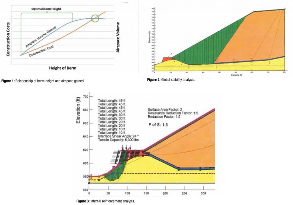
MSE berms can be constructed to just about any height, but a berm in the range of 50 feet high yields the lowest cost per cubic yard (CY) of created airspace. Above that height, more and stronger reinforcement is needed, which adds to costs. Also, the amount of added capacity is finite due to geometry (particularly height), so returns typically diminish beyond 50 feet. The actual optimal height for a facility depends on the availability of land for berm construction and the site geometry. Figure 1 illustrates the relationship between berm height and airspace volume gained.
An MSE berm expansion may not be the lowest cost approach to gain airspace. However, if other methods are not feasible, MSE berm expansions may provide existing landfills with additional cost-effective airspace to extend facility life.
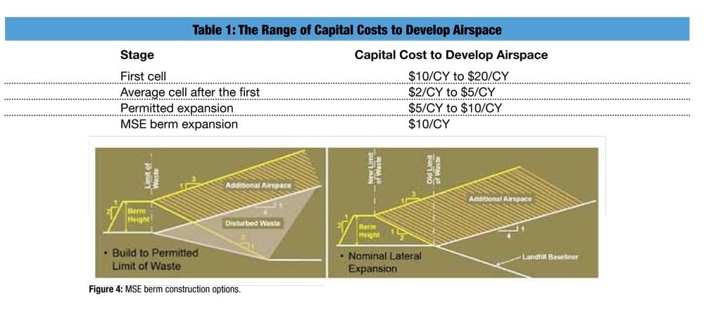
For comparison, the full buildout of a new landfill in the U.S. requires average capital and permitting costs of approximately $2 to $5 per CY of airspace gained over the full life of the landfill. The first cell of this hypothetical new landfill (about 1 million CY capacity) may cost closer to $10 to $20 per CY, when we apply all the capital cost associated with permitting and construction of the initial landfill infrastructure.
Based on recent lateral expansion projects, capital expenditures required to gain this additional 1 million CY through a lateral expansion of an existing landfill without an MSE berm should drop to the range of $5 to $10 per CY of airspace. This is because the expansion should be able to take full advantage of the landfill’s existing infrastructure.
By contrast, an expansion of comparable volume that incorporates an MSE berm for a vertical expansion requires reduced baseliner area and effectively has no additional final cover requirements. However, based upon our recent experience, the berm earthwork and modifications to existing landfill infrastructure can result in a price of approximately $10 per CY of airspace gained.
Therefore, if site constraints preclude a lateral expansion, and roadblocks impede a new landfill development, an MSE berm expansion may be a potential path to new, financially viable airspace. Depending on the amount of airspace required, an MSE berm can certainly be less expensive than the near-term costs of opening a new facility. Table 1 illustrates the range of capital costs to develop airspace.
One factor that may help lower MSE berm construction cost is the use of performance specifications—rather than outsourcing berm design to manufacturers. While outsourcing is perfectly acceptable, and most manufacturers have tools to aid the designer, such an approach can often lead to the use of one specific manufacturer. Instead, consider requesting that the landfill designer prepare a performance specification as part of the actual berm design. The project documents would state the required properties (tensile strength, partial factors of safety, interface strengths and other considerations) rather than specifying a manufacturer’s specific product. This approach leads to a more competitive bid process and will generally lower construction costs.
Base Design Considerations
The general design of MSE walls is not the emphasis of this paper, but the key base design components are summarized below. For more information on established design procedures, consult “Design and Construction of Mechanically Stabilized Earth Walls and Reinforced Soil Slopes” (FHA publication FHWA-NHI-10-024; Nov. 2009). A critical part of the design is identifying allowable tensile strengths; see the Geosynthetic Institute publication GG4(b) for more information.
Global Stability
The first step in designing an MSE berm is to evaluate global stability. This includes evaluating the berm height and width to ensure that potential failure surfaces demonstrate adequate factors of safety. This initial step does not include an evaluation of internal reinforcement and wall stability; it is focused on determining how much the landfill capacity can be increased and the height, slope and size of the reinforced zone. This analysis also confirms whether the berm makes sense from a cost-benefit standpoint. Figure 2 is an example of a typical global stability analysis.
Internal Reinforcement
The next step is a focus on the reinforcement of the berm. General parameters to be considered are the design strength, length and spacing. In addition, backfill parameters (friction angle and density), backfill interface shear properties and geosynthetic reinforcement must also be determined.
Based on our experience, landfill designs with free-draining backfill usually have these features:
- Vertical spacing of about 3 feet for the reinforcement elements. Three feet also corresponds to two typical facing elements.
- Length of reinforcement close to the embankment height. The grids need to be long enough to have embedment to develop enough pullout resistance. However, the length is often controlled by the width determined as part of the global stability step (and/or seismic stability) and is typically greater than what might be required for the berm itself. The optimal design may feature lengths that are greater near the bottom of the berm.
- Tensile strength where the primary reinforcement’s design strengths increase with depth. The trade-off is between optimizing the design with many different strengths or simplifying the design and limiting the types of reinforcement. Up to three primary reinforcement types are typically used.
- Secondary reinforcement with biaxial geogrid is required near the face of the slope to prevent surficial failures on the berm.
Note that the design strengths for the reinforcement must consider long-term effects, including such factors as creep, durability and degradation. GRI GG4b lays this out in detail. Typical design strengths can be three times lower than short-term tensile strengths.
Free-draining sands and gravels are the ideal choice for MSE walls. There is often a desire to use available less-expensive clayey soils. With due attention to saturation conditions and water pressure, constructing a wall with such material may be possible, but is not recommended.
Figure 3, shows the results of a typical internal reinforcement analysis.
External Limiting Eccentricity
Limiting eccentricity is also referred to as overtopping or rotational failure. It applies to walls and is typically not calculated for embankments because it is almost impossible for the embankment to rotate counter clockwise around the toe of slope. Assumptions for rotational failure also include the embankment behaving as a rigid structure, which it is not. Rotational failure can be checked, but it is not the driving factor for design of typical MSE berms at landfills.
External Sliding
Sliding failure considers a situation in which the entire reinforced section of the embankment moves horizontally. Such failure would occur outside of the reinforcement. This analysis is done to ensure that the geogrids are sufficiently long. As noted, grid lengths are usually determined by global stability, so wall sliding is not a controlling factor.
External Bearing Resistance
Bearing resistance evaluates the bearing capacity of the soil beneath the wall to determine the potential for the soil to fail at the toe due to the wall’s weight. This is a function of the foundation beneath the wall and not the wall itself. Foundation conditions with bearing resistance suitable for landfill development should also be suitable for MSE wall construction, but must be checked.
Compound Surfaces
Compound surfaces include various potential failure surfaces that encompass a portion of the reinforced area. These compound surfaces should be checked, because the most critical surface is often one that reaches back into the waste and travels through a portion of the reinforced zone.
Landfill Specifics
The typical design for an MSE berm is a soil slope reinforced with geogrid. The slope has an inclination (from horizontal) of 70 degrees or less, which distinguishes it from a wall. At landfills, wire baskets are usually used to define the face rather than more expensive facing elements like blocks, which are more characteristic of walls. Reinforced slopes with wire baskets are also more flexible than block walls and can easily accommodate minor settlement and horizontal displacement. Aesthetics is addressed by establishing vegetation on the steep slope, but aesthetics is not usually a primary concern at landfills. Also, unlike many other reinforced walls/slopes, landfill reinforced slopes have significant loading (from waste) beyond the backfill. Therefore, implementing an MSE berm into a landfill design requires some design beyond what would be typical for an “embankment only” design.
Significant Waste Slopes Behind the Wall
Usually a large mass exists behind an MSE berm at a landfill. Therefore, the design evaluation must include more global analyses for potential failures that extend back into the waste mass and may extend well past the toe of the wall. An evaluation of seismic loads may further extend the critical surfaces, and the designer may find that additional reinforcement length is necessary to establish a reinforced zone that can support the additional loading.
Permitting
Adding an MSE berm to an existing facility may or may not represent a lateral expansion to the facility. Both approaches are feasible, and we have designed for both considerations. If the existing limit of waste is already at the regulatory minimum setback from the property boundary or some other statutory feature, the MSE berm must be configured to maintain the alignment of the limit of waste. If a final buildout has not been completed, or if there is only nominal additional space between the limit of waste and the statutory limits, the berm can incorporate a nominal lateral expansion of the facility. Figure 4, hows several MSE berm construction options.
Existing Utilities and Infrastructure
While berms can be constructed as part of an initial cell design, they are most often designed to extend the life of an existing landfill that often has significant infrastructure in place. This means that leachate pump stations and/or access points must be extended through the berm. This can often result in the construction of access manholes, as well as the need to reroute underground utilities (electrical lines, force mains and even stormwater pipes) and include them with the berm. Utility poles, guardrail and stormwater channels may also have an impact on berm reinforcement.
Designers must allow for these possibilities, which may result in additional reinforcement. Installation of utility poles and monitoring wells, when drilled through the finished berm, may damage the reinforcement. Designers can allow for these potential future installations through incorporation of sleeves during earthfill operations. Calculations should be sure to make allowances for the loading and space required for the drill rig. The designer also must remember that the lined inside slope of the berm needs to be tied into the existing cell. Figure 5, shows MSE berm construction around existing landfill infrastructure.
Sequencing and Landfill Operations
MSE berms are often constructed to extend the life of current landfills, which means construction is usually done at active landfills. Care must be taken not to hinder current operations. In addition, the berms typically encompass multiple cells and could be more than a thousand feet long, so they are often constructed in phases. Sequencing the berms and ultimately determining how they should be tied together is an important consideration.
Take a Second Look at Sites Thought to be Un-Expandable
The point of this article is to challenge facility owners and designers to take a second look at existing facilities that were thought to be un-expandable. Our experience has shown that MSE berms do offer an excellent, practical tool for expanding capacity and extending the life of existing landfill facilities.
Don Hullings is a Client Manager with Cornerstone, A Tetra Tech Company (Middletown, NY), and has 28 years of experience in the solid waste industry. He is a technical expert with extensive experience in integrated solid waste planning, design, engineering, permitting and construction for landfill expansion projects, specializing in geosynthetic and geotechnical engineering, landfill permitting, and landfill optimization. He can be reached at [email protected].
Bodhi Piedmont-Fleischmann is a licensed Environmental Engineer with Cornerstone, A Tetra Tech Company, with experience in transfer station permitting and reporting, landfill cell design, and client administration. Her project work includes preparing solid waste facility permit applications, certification reports, operations and maintenance manuals, contingency plans, environmental health impact drawings and reports, engineering drawings and reports, engineering quantity and cost estimates, landfill cell and capping construction documents, stormwater and leachate collection system design, preparing technical specifications, and landfill gas collection system design. Bodhi can be reached at [email protected].
Kirstie Shurie is a Staff Engineer with Cornerstone, A Tetra Tech Company. She has two years of experience providing assistance to Project Managers on landfill design, engineering and permitting projects, leachate system design projects, stormwater control design projects, landfill gas system design projects, and construction quality assurance (CQA) projects, among others. Kirstie studied chemical engineering design, energy systems, and process dynamics and controls. She can be reached at [email protected].
You may also like:
3 Tips for Modernizing Your Landfill and Waste Management Plan